PRELIMINARY INFORMATION - SUBJECT TO CHANGE
The ROVotron transmitter uses one or two Sony PS2 Dual Shock 2 controllers and a custom microcontroller-based interface to the tether. An RS-485 serial link is used for data transmission. A matching microcontroller in the ROV receiver decodes the serial command stream and returns telemetry data.
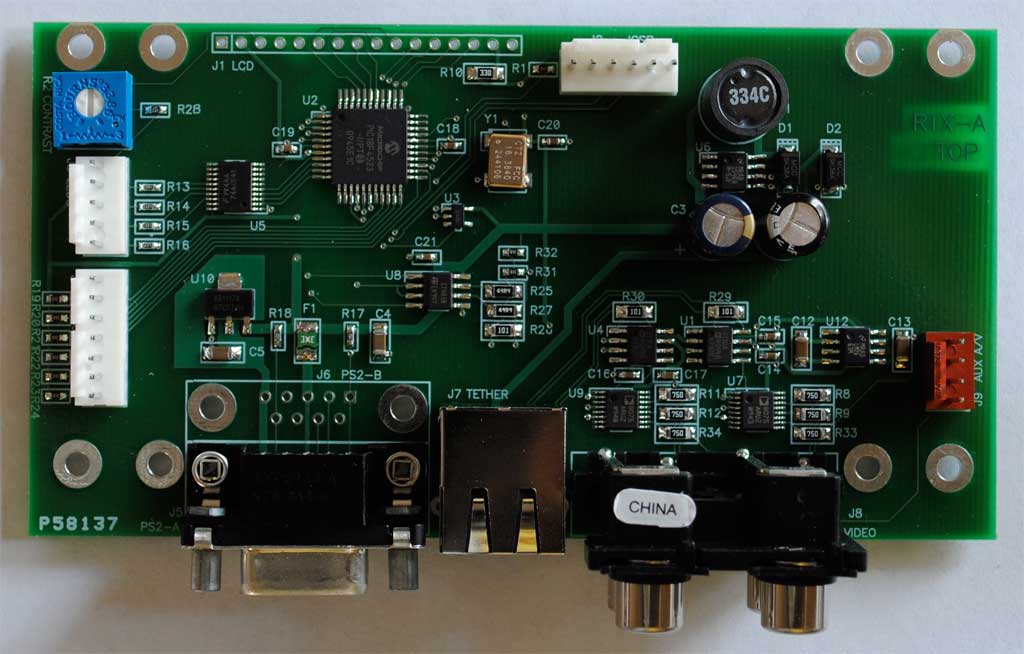
Transmitter box
The ROVotron transmitter is a clear plastic box which houses the following items:
- An RTX transmitter PC board
- An LCD display, 4 x 20 characters with backlight
- Switches (e.g., for arming and launching torpedoes)
- LEDs to indicate ROV status (e.g., torpedo launcher ready)
The front edge of the box has the following connectors:
- One or two DE-9S for PS2 controller(s)
- An RJ45 jack for the signal tether
- Four RCA jacks for audio and video outputs
The RTX board has the following onboard connectors:
- A 7 pin Molex for up to 6 switches
- A 5 pin Molex for up to 4 LEDs
- A 4 pin Molex for a third A/V feed
- A 6 pin Molex for a PIC programmer
Refer to the schematics Transmitter page 1 and Transmitter page 2 to follow along with the text below.
Tether interface
The tether is one 16 AWG zip cord plus one CAT-5 cable, since we only need three signal pairs: RS-485, video and audio. Fused 48V power to the transmitter box is sent over the fourth pair from the ROV to eliminate ground loops.
We use a standard RS-485 transceiver chip. The termination has a divide-by-3 function to reduce voltage swing, which also reduces power consumption and EMI generation. The receiver still sees 1.3V which is enough for the differential detector to work just fine over our cable length. The divider network can be changed or bypassed as needed.
PlayStation2 interface
The command transmitter uses a standard Sony PS2 DualShock2 controller or two. This device provides two joysticks, two button diamonds, two trigger button pairs and Select and Start buttons. It features an analog mode that provides pressure data from the buttons to allow their use as speed controls.
The interface to the PS2 controller has been figured out by nice pople such asCurious Inventor. It's an SPI interface. The pinout is shown below.
The pinout we use matches the pinout of the factory connector, which is unobtanium. So we cut it off and wire in a DE-9P.
| Pin | Name | Dir | CPU |
|---|---|---|---|
| 1 | Dat | in | SDI |
| 2 | Cmd | out | SDO |
| 3 | MPwr | out | Vcc5 fused |
| 4 | Gnd | -- | Gnd |
| 5 | Vcc | out | Vcc3 |
| 6 | Atn | out | ATNA, ATNB |
| 7 | Clk | out | SCK |
| 8 | -- | -- | -- |
| 9 | Ack | in | ACK |