PRELIMINARY INFORMATION - SUBJECT TO CHANGE
The speed controller board RSC has two 10 Amp pulse width modulated (PWM) motor controllers and a pair of digital open-drain outputs. It is intended to control two 12V DC motors such as the Rule 1100 GPH bilge pump motors. The speed commands come from a parallel data bus. The motors are powered from a 48VDC power bus.
Features
- Powered from 48VDC to allow use with a lightweight tether cable
- Powers and provides bidirectional speed control for two 10 Amp, 12V motors
- Provides two 10 Amp MOSFET low-side switch outputs, one NO and one NC
Power and signals
- DC power inputs: 48V and 12V and 3.3V on backplane connector
- Control input: parallel address/data bus on backplane connector
- Motor outputs: Two 10 Amp PWM motor pairs on a 4-pin screw terminal block
- Switch outputs: Two 10 Amp switches and Gnd on a 3-pin screw terminal block
Refer to the schematics Speed controller page 1 and Speed controller page 2 to follow along with the text below.
See the receiver board description for the backplane signal protocol.
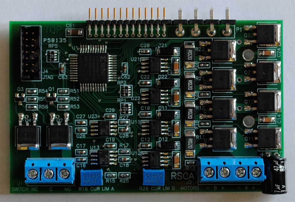
Front connectors
The front edge of the board has a three-pin screw terminal block for the switch outputs and a four-pin screw terminal block for the motors. The blocks are labeled as to function.
Switch outputs
A 48V, 10A switch output is provided for each of two switch channels. One side of each switch is connected to Ground, so they may only be used to ground something.
Each is driven from logic by a 12V transistor level shifter. There is one normally-closed output and one normally-open output. The inactive state is entered on powerup to prevent mishaps.
Motor drive
Each motor uses a duty cycle of 25% to achieve full motor power. This allows the board to drive two motors, each in its own 31 KHz PWM time slot, to draw less than 5A from the 48V battery. Since the supply voltage is 4x the rated motor voltage, a 25% duty cycle will produce full motor power as it makes the full 12V-equivalent current in the motor.
A half-bridge driver IC drives the gates of each pair of high and low side MOSFETs. It requires a 12VDC power source and accepts two TTL gate enable signals.
The motor current is continually sensed to ensure that the motor doesn't burn out if stalled. A sense resistor on each low side switch source develops voltage proportional to current; 0.02 ohm gives 0.2V for 10A current. A pair of comparators monitor the voltage across the two current sense resistors. Two comparators are used because either low-side switch may have the continuous motor current across it, depending on the motor direction.
If either comparator detects an overcurrent condition, it pulls the FAULT signal low, which tells the CPLD to turn off the current to the motor in question until it drops to a safe level.
Each comparator input has a low-pass filter to measure average current. The time constant is 3 PWM cycles. This ensures that the average current of the motor is being measured, rather than any switching transients.
The comparator voltage reference is an adjustable voltage divider driven by the 3.3V supply. The adjustment range is 0 to 0.2 volt for a 0 to 10 Amp current limit range using a 0.02 ohm resistor.
Controller
The controller is implemented in a XCR3064XL Complex Programmable Logic Device (CPLD). This part can be programmed to implement just about any logic function desired, as long as it has 64 or fewer internal register bits.
See the source files here:
rsca.vhd Main VHDL source file
rsca.ucf Pinout and constraint file
busin.vhd Bus input VHDL source file
pwm.vhd PWM VHDL source file
The CPLD is programmed with two PWM motor drivers. Each motor driver converts an 8 bit speed command to a 31.25 kHz PWM stream whose duty cycle ranges of 0 to 25%. The direction bit steers the pulses to the proper H bridge driver inputs to feed positive voltage to the motor during forward operation and negative voltage during reverse operation.
During the inactive state, between PWM pulses, the motor winding is shorted by holding both motor terminals low to keep the motor current flowing. Since the current sense resistors are in series with the low side MOSFETs, the current sensing circuit is still active while the motor is shorted.
The MOSFETs are all turned off for one clock cycle (60 nanoseconds) of "dead time" while switching from active mode to inactive and back to prevent "shoot-through" in which the MOSFETs cause a short circuit across the 48V power supply.
The two motors are synchronized to a master Phase signal from the receiver board. This signal is a 62.5 kHz square wave. The two motors are enabled during alternate cycles of Phase for current time-sharing.
A signal Slot identifies whether the controller should enable the PWM during the high or low periods of Phase. This time-shares current between adjacent boards. The result of the time-sharing is that each motor receives a maximum of 25% ON time.
The PWM downcounter runs at 16.384 MHz for up to 127 counts. There are three dead counts per phase for a total of 130 clock cycles per phase. The PWM frequency is exactly twice 15.75 kHz, which is the video scan line rate. this means that any video interference is stationary in the display, so is easy to ignore.
Mechanical
The RSC speed controller board is designed to plug into the RRX receiver-backplane. Up to five RSC may be plugged into the RRX in a stack. The RRX is mounted to a pair of card guides that position the RSC boards.
The MOSFET transistors are Fairchild type FDD3672 in the small surface-mount DPAK package. Each RSC has a heat sink covering the MOSFETs and extending over the edge to slide into the card cage for conductive cooling. A pair of screws hold the heatsink to the card cage, ensuring a low thermal resistance path from the transistors to the frame.